| Photo of the month – October 2017 |
[German version] |
Pulverized crate
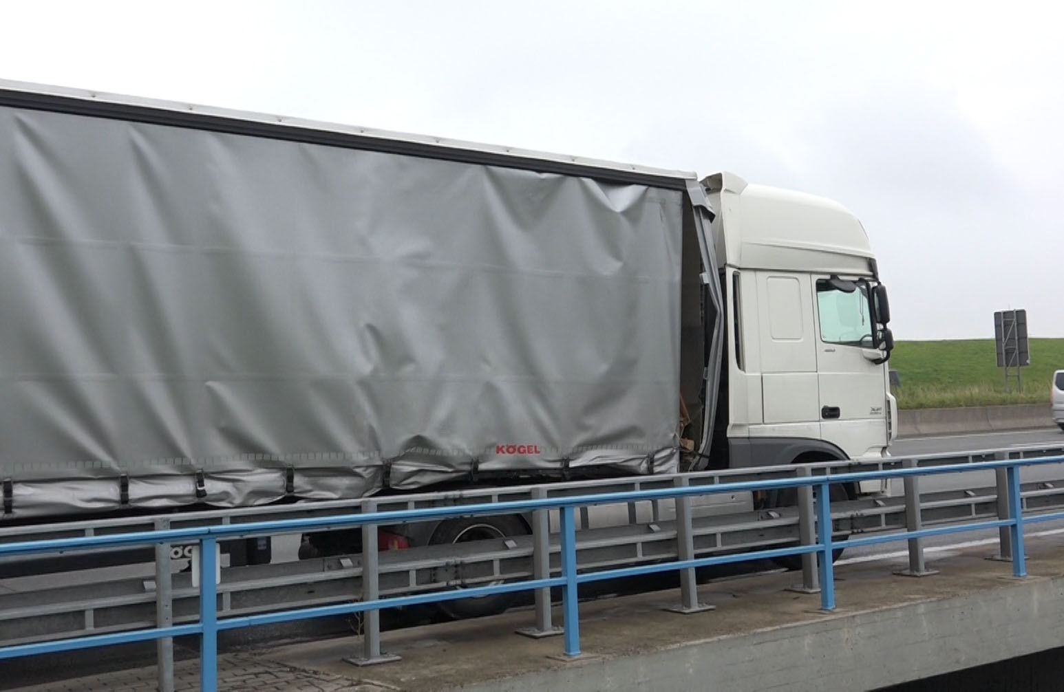
Figure 1 [Video News 24]
Once upon a time, a curtainsider articulated truck was standing on the hard shoulder of the motorway and its curtain was looking the worse for wear, as was its end wall. This vehicle, or at least what had happened to it, aroused the curiosity of this team of load-securing columnists. The fact that the end wall appears to be severely buckled and one of the curtains is hanging loose could indicate that the vehicle had once been home to a load with an irresistible taste for freedom.
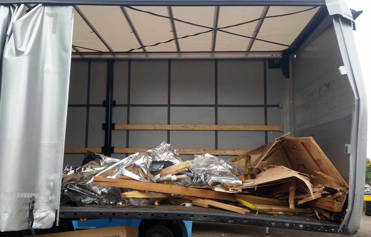
Figure 2 [Wolfgang Jaspers]
And we were not wrong. If we pull aside the curtain, we can see that it is not only the end wall that has been destroyed. The front right of the loading bed has also been bent downwards considerably. On the loading bed, it would seem that it was the weekly trash from a packaging company that was being transported, and yet it is only a crate that has been pulverized. But because trash of this kind is generally separated and compressed before disposal, we quickly dropped that conjecture. But now we wanted to know the truth. With our detective's hats on, we worked our way through a veritable plethora of photos to get to the bottom of this case.
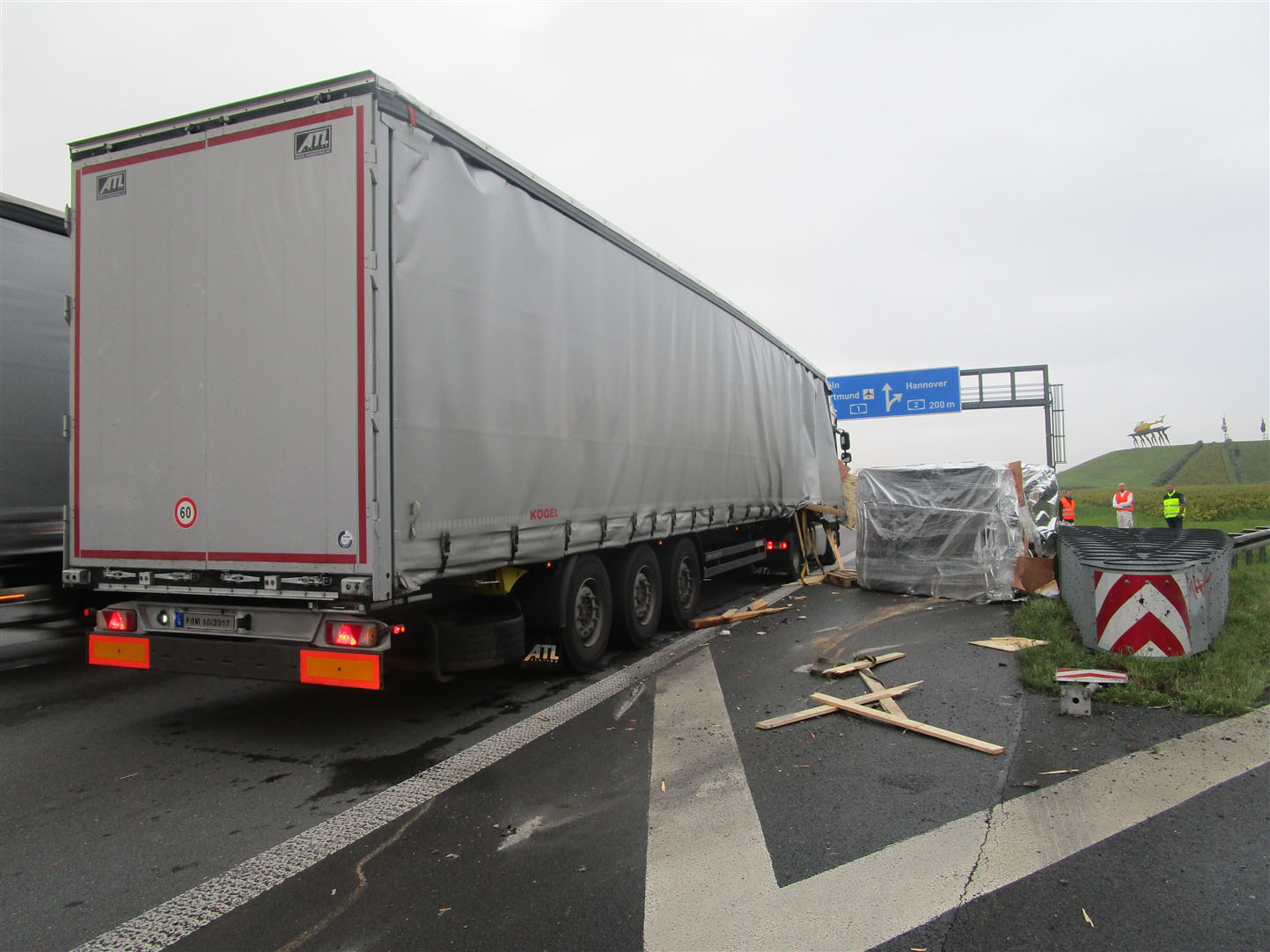
Figure 3 [Dortmund Police]
Figures 1 and 2 were not hugely enlightening, but Figure 3 tells us almost all we need to know. We can see an articulated truck standing on the right-hand lane of a motorway. It has clearly shed its load to the right. When questioned, the driver said that he had to brake sharply at the end of a tailback. This caused the load to start moving, but it fortunately fell from the vehicle onto the hard shoulder on the right.
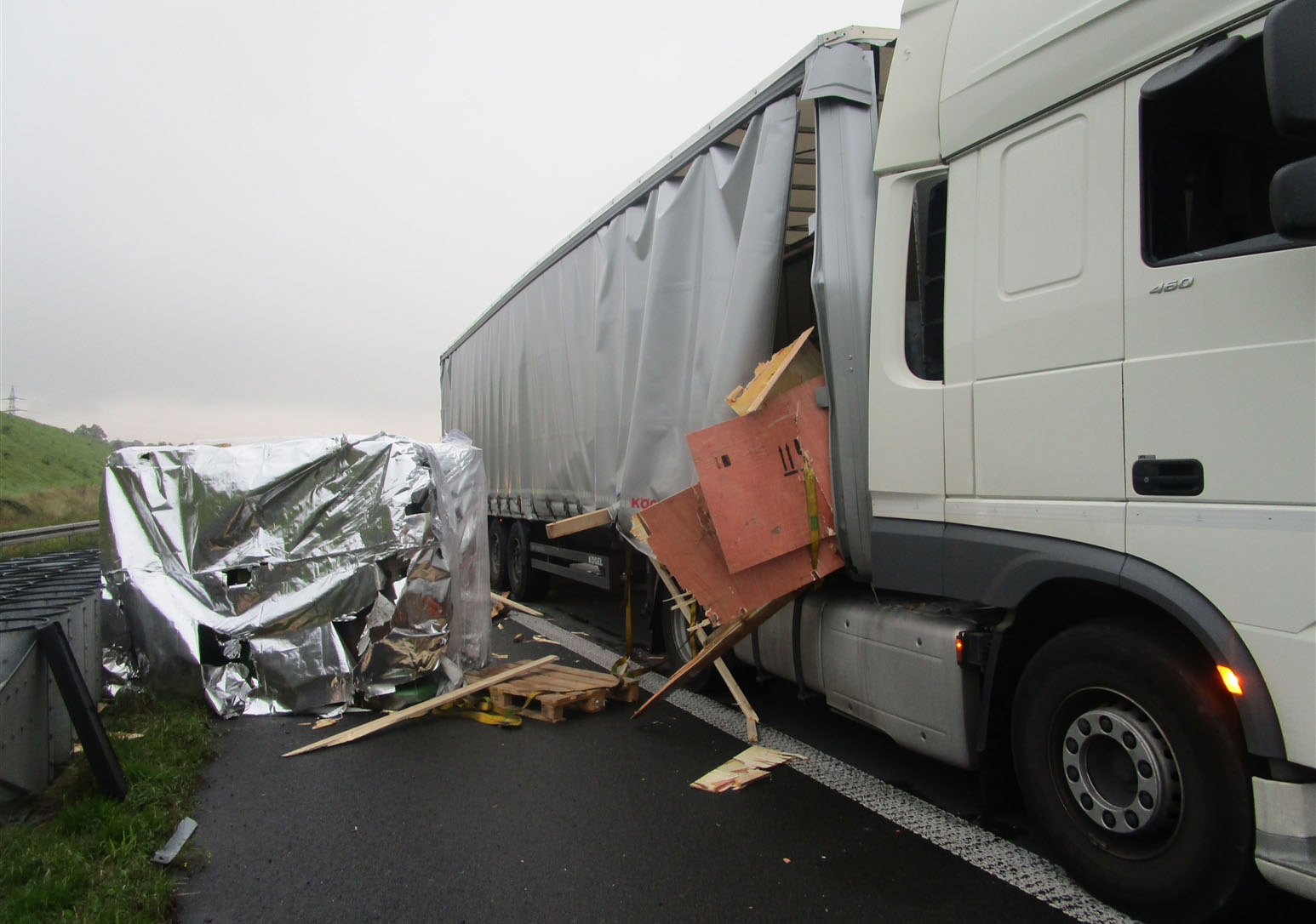
Figure 4 [Dortmund Police]
The load itself was a sheet metal press. This was clearly wrapped in airtight packaging intended to protect it from corrosion. It would appear that the press was originally packed in a crate that was lashed down to the vehicle with 2 or 4 lashing belts.
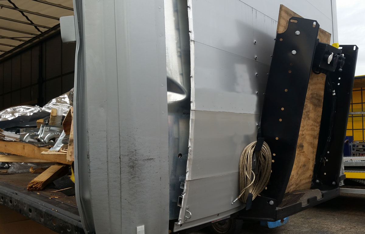
Figure 5 [Wolfgang Jaspers]
Figure 5 is also extremely revealing, and testifies to the amount of kinetic energy that was converted to deformation energy at the end wall. The end wall has been torn out of its side support. The black vertical supports (in front of the end wall) were bent forwards considerably and the corner post or beam has been massively deformed. As we have already noted, the loading bed has been bent downwards. This is because the 14.4 tonne sheet metal press slid over this front right corner and fell to the road where it could enjoy its "freedom", as we saw in Figure 3. The marks on the road surface also tell a tale. They describe how the machine hit the road, probably "tumbled" and came to rest on its side.
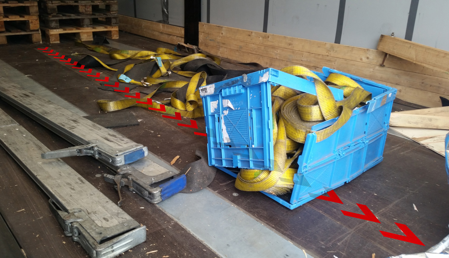
Figure 6 [Wolfgang Jaspers]
Your immediate reaction may be to ask why we have chosen this thoroughly untidy photo as our sixth photo. The photo may not appear to tell a tale immediately, but it nevertheless contains a lot of information. We have highlighted one of the two skid marks left by the crate containing the sheet metal press with a series of arrows. As we would expect from a normal load distribution plan, the crate had probably been placed with its center of gravity just in front of the first axle unit. This means that its front edge slipped somewhere between 4.5 and 5 m before it reached the end wall. This is also confirmed by a number of other photos that we were able to see. On the loading bed, we found not only belts that had clearly been sliced through or had torn apart (probably as a result of the sharp edges of the crate), but also heaps of anti-slip material and a blue box, or what was left of it, packed full of more load-securing materials. We did not see any crumbled anti-slip mats, either on Figure 6 or on any other photos of the loading bed, but instead only more or less intact mats. And because the skid marks on the loading surface tend to suggest wood slipping over textured, coated board, we assume that not one anti-slip mat was actually used. It was not a lack of load-securing material, but rather a lack of knowledge that it is not possible to secure this load of 14.4 tonnes plus the weight of the packaging with just 2 or 4 tie-down lashings and that rather more extensive load securing measures would be necessary. The remains of the crate that we can see on the photos do not allow us to judge whether the sheet metal press was secured properly in the crate. But it is a fact that the load was secured dreadfully.
Let us first look at the tie-down lashings:
In this case, a crate with a gross weight of something around 14,600 kg or 14,800 kg was secured with tie-down lashings. The job of a crate is to protect the load it contains from external influences. It need not always be designed to withstand the forces generated by a tie-down lashing, in particular if tie-down lashings are not the best way to secure the load. Assuming that the crate is to be secured by tie-down lashings and that anti-slip materials are used, the loads on the top of the crate would be as follows: 0.8 – 0.6 (for μ) = 0.2. 0.2 x 14,600 = 2920 daN necessary residual securing force to the front. 2920 daN / 0.6 (for the good friction provided by the anti-slip material) = 4867 daN pre-tensioning force required to secure the crate with tie-down lashings. Not all crate tops are designed to be able withstand such loads.
Recommended load securing method:
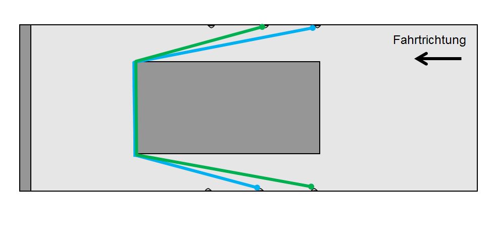
Before we start, we should point out that a load like this can be secured in a number of different ways, but we shall only show one method here. Sufficient anti-slip material should be placed beneath the crate to ensure that there is absolutely no direct friction contact between the crate and the loading surface. This does not mean that anti-slip material has to be placed beneath the entire crate. It does, however, mean that no other part of the bottom of the crate is permitted to touch the loading bed. The best way to check this is with a sheet of paper. It must be possible to push a sheet of paper under the bottom member wherever the crate is not permitted to touch the loading surface. It is even better if you can see a light shine through under the bottom member. This means that it has no direct friction contact with the loading bed. Only if this is the case is it possible to calculate using the good coefficient of friction μ of 0.6 provided by the anti-slip material. To ensure that this good level of friction is not lost as a result of vibrations and oscillations during transit, at least two tie-down lashings are recommended in order to provide a minimal level of load securing. It is, of course, necessary to protect the belts from the sharp edges of the crate. Our assumption that the load weighs 14,600 kg means that the securing force still required to the front is 4867 daN, so we would use two direct lashings to secure the load. In this case, we assume that the top of the crate was not strong enough for tie-down lashings or any kind of direct lashing. However, it must be sufficiently strong at the bottom, as the cargo itself must be bolted to the floor of the crate securely. The belts must therefore be arranged in such a way that they take the weight of the crate at its base or floor. In other words, the force from the floor of the crate must be able to be transmitted to the belts as directly as possible in order to secure the crate effectively. The two belts should be arranged asymmetrically, i.e. placed alternately on parallel load securing points so that the belts are both of an identical length (see diagram).
Sketch [GDV]
If this is not done, the shorter belt first has to take up the majority of the force, and the longer belt is not loaded at all or is not subject to as high a load, which could cause this securing arrangement to fail.
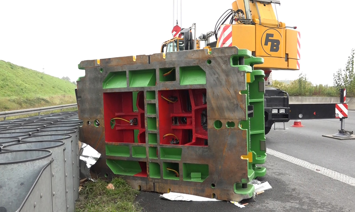
Figure 7 [Video News 24]
Responsibility for load securing:
We would also like to talk about the many layers of responsibility in respect of load securing.
- A crate must, of course, be constructed in such a way that the cargo in the crate is joined to the floor of the crate in such a way that it cannot escape under normal conditions (0.8 to the front and 0.5 to the sides and rear). We cannot judge the quality of the crate from the debris left behind, so we have to assume that this was the case.
- The loader, for instance the person who packaged this sheet metal press and placed it on a truck, also bears the responsibilities of a loader. This person must assist in securing the load and may not allow the truck to leave the premises if the load is not safe for transport. In the light of the blatant shortcomings in securing this load, the loader takes the same share of the blame as the driver. Subjectively, we feel that the loader has a greater share of the responsibility, as the loader is the client and the driver is only a tool of the carrier, and plays the smallest instrument in the concert that is a transport operation.
- The driver, of course, bears responsibility for ensuring that his load is secured in such a way that it is safe for use and transportation. But he cannot live up to this responsibility if he has not received sound training in load securing. As far as training is concerned, we see this firmly as the duty of the carrier.
We should also note that this sheet metal press is undoubtedly not where it was expected to be. Perhaps a production process has been interrupted for weeks or months. And all this simply because somewhere one or two people neglected their responsibilities and could not be bothered with a few rubber mats and a couple of properly arranged belts. That's a pity!
Finally, we would like to note that it was purely a matter of luck that this sheet metal press did not fall from the left of the vehicle and into the traffic, where it would have done far more damage than neatly bending sheets of metal.
Your load securing columnists as always wish you a safe journey!
Back to beginning
