
| Photo of the month – June 2024 |
[German version] |
Tiny House on the Road

Figure 1 [Holger Kastner]
Here’s something new!
An entire house on the move on the back of a low-loader. Houses like these are not really made to be transported. Maybe they can be moved just the once but the necessary prerequisites such as attachment points for lifting or load securing points rarely come as standard. So let’s take a closer look:
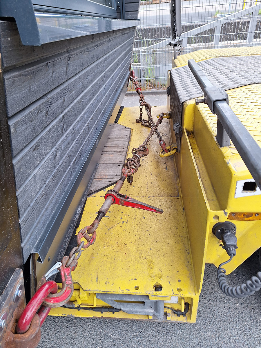
Figure 2 [Holger Kastner]
And here, indeed, we have some load securing points, which are the main focus of interest today. This is because we do not always find standardized, welded securing points with the corresponding lashing capacity (LC) marked on them. In the case we are looking at here, that is precisely the problem. However, the parties involved clearly thought about what was involved. The form of securing we can see here has been attached at the back and secures the load to the sides Typically, load securing points located at the back (see middle of vehicle) of low-loaders such as this are attached in such a way that they can primarily absorb loads in a variety of angles in the direction of travel. It is much more difficult for them to absorb lateral forces because they must be rotated through 90° in order to do so. However, we are unable to say what level of force they are able to absorb when loaded as shown in the current figure. But first of all, let us see what they actually have to do in this (special) case.
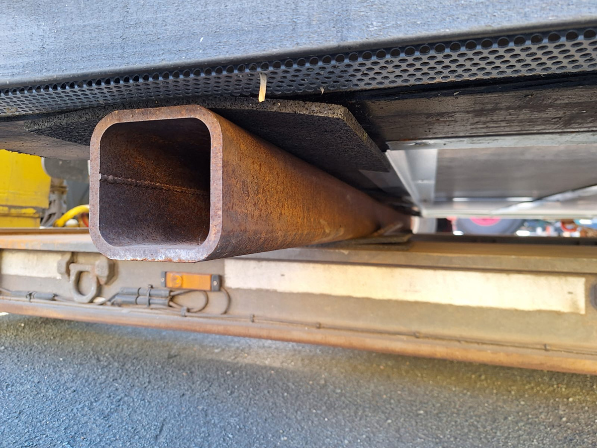
Figure 3 [Holger Kastner]
The first step is to take a look at the friction. And here again, some thought was given to the problem! Since it is possible to position the house on lifting gear in order to handle it, it is here standing on square tubes. A sufficient amount of anti-slip material has been placed above and below these, with the result that, in terms of friction, the house is completely isolated from the steel and the steel completely isolated from the loading surface. We can therefore perfectly happily assume friction of μ = 0.6. This means that the load securing arrangements to the side only have to provide the minimum securing force and they are most certainly able to do that in the case we are looking at here.
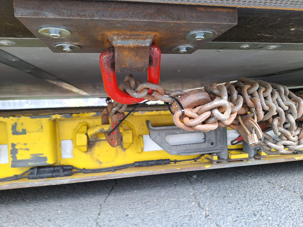
Figure 4 [Holger Kastner]
Another lateral securing element was found underneath the load. Here, the load securing point was attached correctly and the chain was “threaded through” – although that is an arrangement we are not particularly fond of, the chain in this case nonetheless completely fulfilled its function.
However, the key focus of this month’s article is and continues to be the connection between the load securing points and the house.
Because no one is able to say exactly how this functions here, we will have to rely on simple rules of thumb in order to come to an estimate (no more, but also no less).
So what do we have?
- Steel plates of approximately 8 -12 mm in thickness to which the load securing points were welded. There can be no doubt that they were up to the job.
- These plates were screwed to the house with four 8×240-mm wood screws. We can see washers between the screw heads and the plates. The screws are not countersunk but instead stand slightly proud.
- At first sight, this connection seems to be the real weak point in the load securing arrangement. And that is not just our opinion but also that of the inspecting officials on the scene.
- We therefore decided to take a rather closer look. We assume that the screws were made from steel of quality grade “8”. This means they had tensile strength of 800N/mm². This quality class corresponds to the 0815 steel which was once commonly used to manufacture load securing chains. However, it is perfectly possible that these screws were made from a higher-grade steel. We have no information about this and therefore the above specification is merely an assumption.
- Given a screw of diameter 8 mm (Pi x r⊂), the surface area is 50.24 mmr⊂.
- Grade 8 steel has tensile strength of 800 n/mm² which, multiplied by 50.24, gives us 40,192 N = 4,019 daN
- However, what is in question here is the shear strength of the screws. Once again, we can call on a rule of thumb that tends to err on the cautious side. This says that the shear strength can be assumed to be 40 % of the tensile strength. This leaves us with 1,608 daN
- However, since up to now all our calculations have been based on the breaking load, we need to apply a safety factor of at least two, and a factor of three would be better. Using a factor of two, we have a shear strength per screw of 804 daN and with a safety factor of three, a shear strength of 536 daN.
- Since there are four screws per plate, we can multiply these forces by 4 to obtain an LC value of 2,144 daN.
- Here again, it is important to point out that these values have been calculated using rules of thumb. These are used now and have been used in the past in the maritime sector, where materials whose properties are unknown are frequently used.
- Now that we have a known LC value for the four screws, let us check the strains that the load securing equipment must withstand.
- To the side, we are lacking only the minimum securing force, which is almost always provided by means of a tie-down lashing. This approach to load securing is not possible here and so direct lashings were used instead. Although the connections of the load securing points to the house are the weak point in the load securing arrangements, they nevertheless provide two times 2,144 daN of securing force. A minimum securing force of 4,288 daN is sufficient and the securing arrangements to the side are therefore in order.
- In the longitudinal direction, the load was also secured with two direct lashings. There were no losses due to angles and the securing force of two times 2,144 daN, that is to say 4,288 daN, can therefore be taken over in full.
- The house weighs 11.5 tonnes. It is underlain at all points by anti-slip material and a coefficient of friction of µ = 0.6 can therefore be assumed. We are still missing 0.2 times the weight of the load in securing force. 1.15 x 2 = 2.3, which corresponds to a shortfall in securing force of 2,300 daN. Since the two load securing points provide 4,288 daN of securing force, the load is adequately secured.
For us, too, this is a surprising result. Of course, this does not mean that load securing requirements should be calculated using rules of thumb in the future. Anything but! However, this example does show that these rules can provide a good estimate, but nothing more than that.
What should be done in such cases? The person who came up with these load securing arrangements must have known or been able to calculate the shear strength of the screws better than we have done with our rules of thumb. Documentary proof of this calculation must be produced and should accompany the transporting vehicle. Consequently, the responsibility for the safety of the load securing points lies with this person. The company’s management must make sure that the person in question is able to calculate the shear strength, as otherwise the responsibility falls on management.
It is out of the question for police officers, drivers and/or loading personnel to have to occupy themselves with such questions out on the road. - This connection would undoubtedly withstand a lot but the load securing equipment together with the load securing points were completely overdimensioned for the task at hand. This is undoubtedly because they are used very frequently and for very different loads.
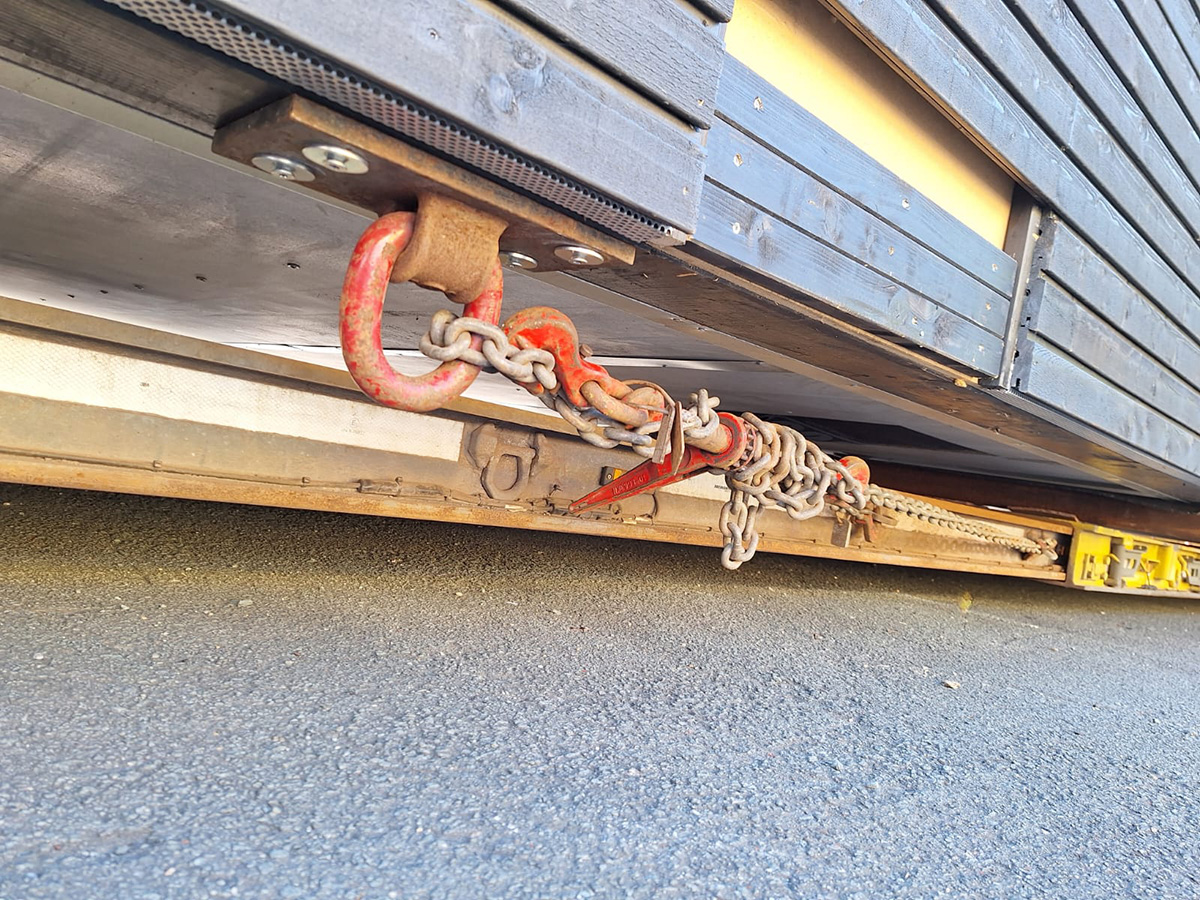
Figure 5 [Holger Kastner]
The load securing point shown in Figure 5 is once again attached incorrectly. Of course, it can still absorb forces even like this. However, the eye should be welded to the plate rotated through 90&grad;. According to the rule of thumb above, the load will still be adequately restrained even though the load securing point was incorrectly mounted rotated through 90&grad;. The geometry of the chain shows that it is well-tensioned since it sags, if at all, only by one or two millimeters. We have no information about why the securing in the direction of travel was attached under the house and can only assume that it was to avoid damaging its visual appearance, because any attached load securing points would leave marks.
It would also be possible to support the house against the front of the trailer. However, that might also leave marks and, in addition, load-bearing elements of the house would have to be located there.
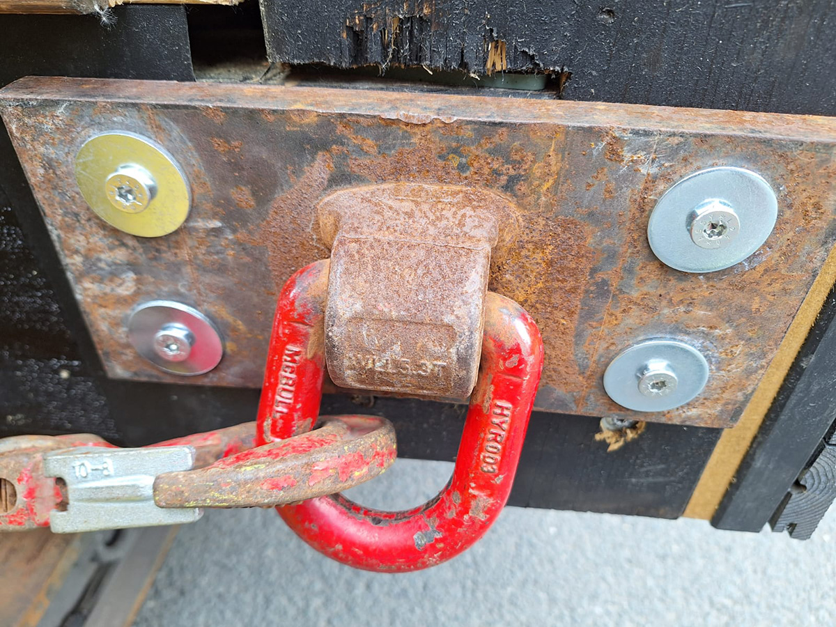
Figure 6 [Holger Kastner]
In Figure 6, we once again immediately see the geometrical mismatch between the load and the design of the elements. Here again, if the load securing point had been welded to the plate rotated through 90&grad; then the forces would flow “naturally”. Alternatively, it is possible that the plate was screwed on rotated through 90°, i.e. vertically.
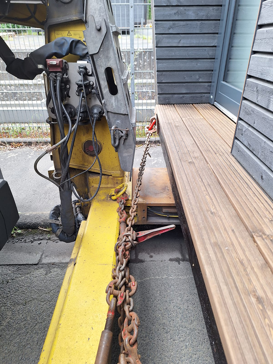
Figure 7 [Holger Kastner]
Figure 7 shows the lack of a tight fit to the front.
Your load securing columnists wish you a pleasant, safe and secure start to the summer!.
Back to beginning