| Photo of the month – January 2023 |
[German version] |
Folding pallets?
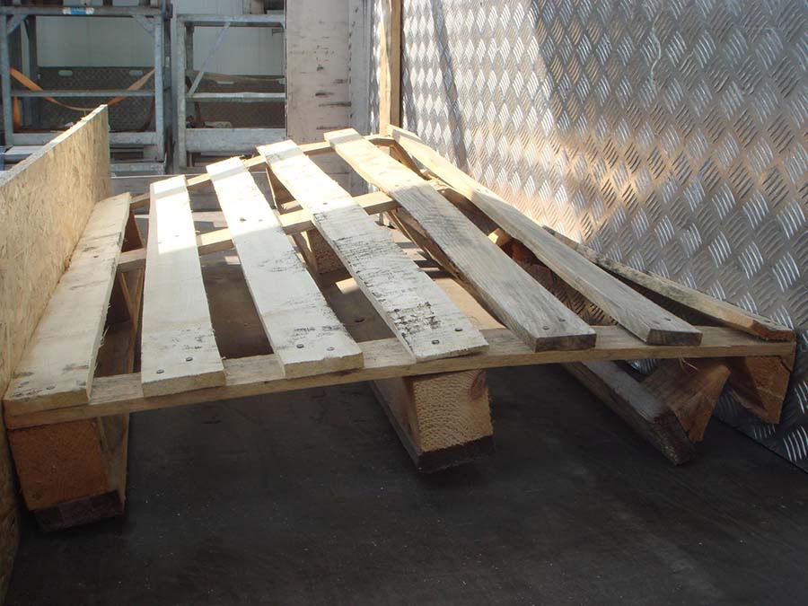
Figure 1 [Karl-Heinz Pachoinig]
The flexible, folding pallet is a new kind of base that can be used in a variety of ways to form a load unit. When subjected to a load, it demonstrates unexpected capabilities, as can be seen clearly in this photo. One question immediately sprang to mind: How did the pallet become so elegantly deformed?
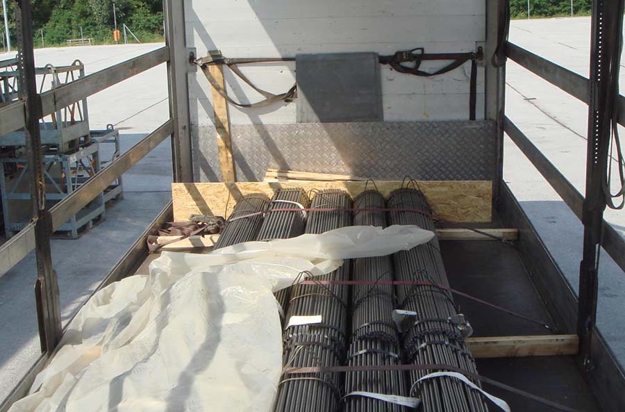
Figure 2 [Karl-Heinz Pachoinig]
Figure 2 shows part of a cargo of bundles of metal rods, possibly steel, loaded as a good tight fit next to each other and to an artificial end wall. We can just about make out the pallet behind this end wall.
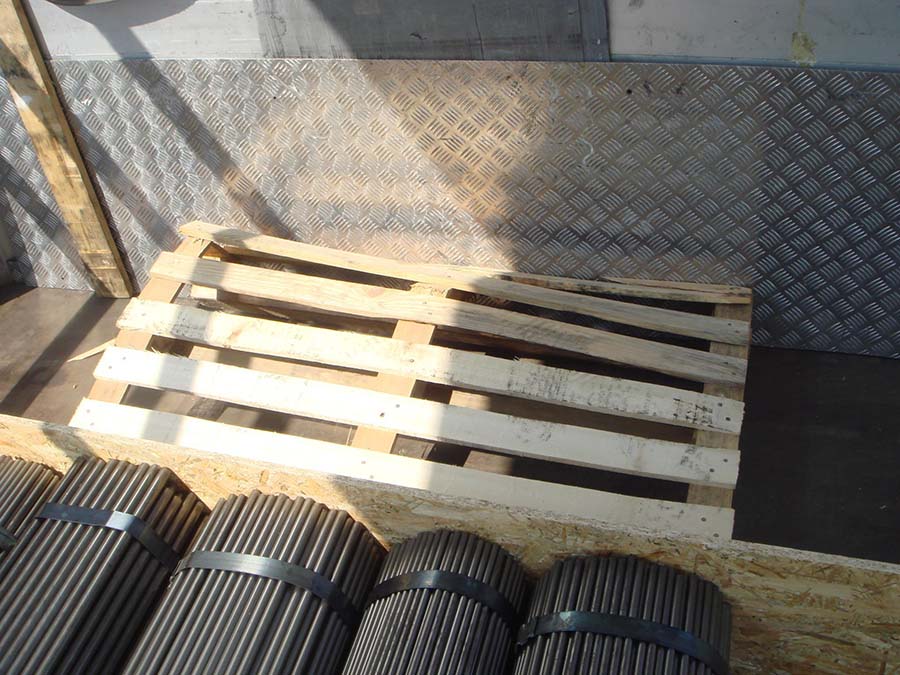
Figure 3 [Karl-Heinz Pachoinig]
This photo (Figure 3) reveals the whole truth about what we can only call a hefty miscalculation. A full load of steel, comprising bundled rods and angle sections, was loaded up against a pallet using a sheet of OSB to distribute the forces. Perhaps the term “pallet” is too generous for this example of the breed, which is a single-use, lightweight construction of dubious quality! Just three thin boards are expected to hold up against a a good 24,000 kg load of steel slipping gently forwards. Nothing spectacular had happened. The vehicle had simply braked a little in traffic, and the pallet yielded to the inevitable. Whoever was responsible for securing this load would not even trust these three thin boards to support them to cross a small stream with dry feet. But they were still happy to entrust them with providing tight fit securing for 24,000 kg of steel.
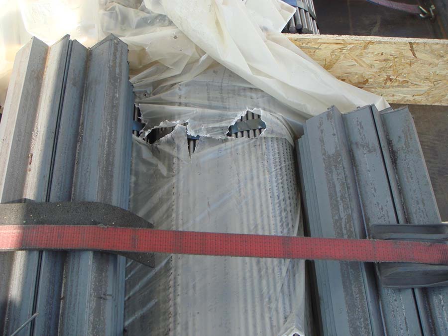
Figure 4 [Karl-Heinz Pachoinig]
If we take a closer look, we can see that even the tight fit was not as successful as we may have hoped. There was clearly no plan behind the use of the plastic sheeting. And this is rather worrying, because the sheeting can, at least in places, have a negative impact on friction.
Those readers who are familiar with our column will immediately start by asking how the load was secured. We can’t say for sure, as we don’t have a photo that shows the whole load. But we assume that six tie-down lashings with an angle of around 30° were used and no anti-slip material was deployed. A pre-tensioning force of 500 daN on each side gives 1000 daN per belt. The unfavorable angles reduce the effectiveness of the lashings by 50% and the coefficient of friction μ can be assumed to be 0.3 at most. Because plastic sheeting has been used in the middle of the load block, we would prefer to assume a coefficient of friction μ of 0.25. This provides a calculated securing force of 3000 x 0.25 = 750 daN, compared with the total of 13,200 daN that would actually have been needed.
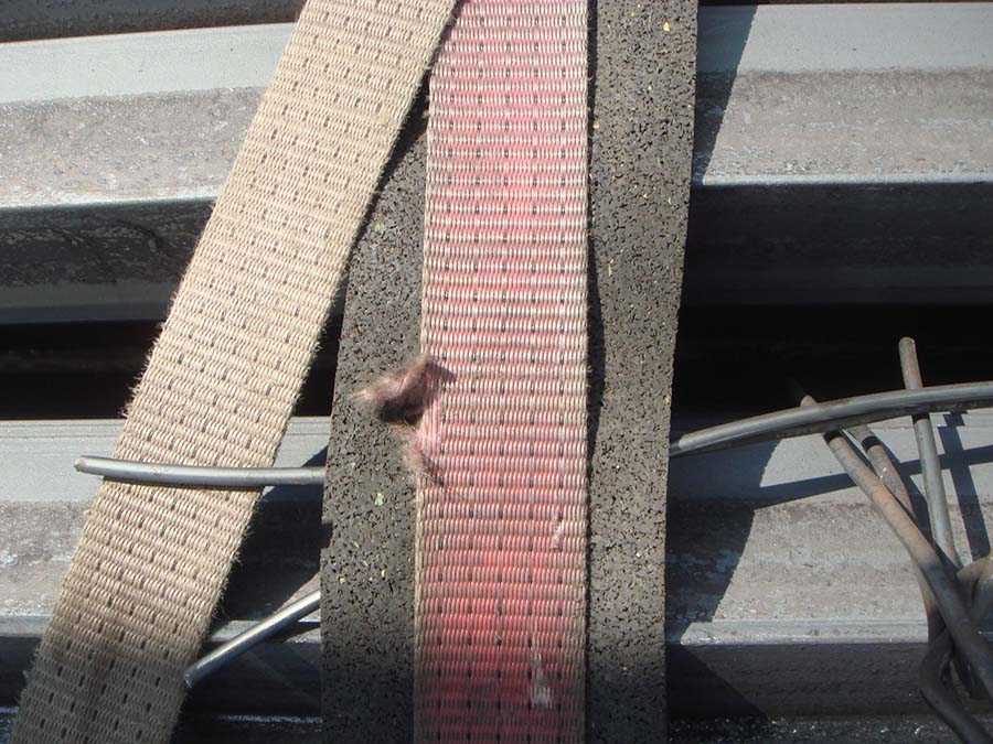
Figure 5 [Karl-Heinz Pachoinig]
We have not even taken into account that some of the belts were fit to be scrapped and that anti-slip material was generally used as edge protection. Perhaps we should say a little more about friction: We know that we tend to go on endlessly about friction, but it is a simple fact that everything to do with securing a load revolves around friction. If the decision is taken to use tie-down lashings, it makes sense to use proper edge protectors that allow the securing force to be distributed evenly over both sides. But in this case, this was not done anywhere. Instead, anti-slip material was used to provide edge protection, but this achieves the opposite effect. The high level of friction ensures that there is at best only a slight distribution of the securing force. And so, even though the way in which this load was secured was already frightful, the laws of physics were commandeered to make it worse. Bizarrely, the loaders failed to place any anti-slip materials under the load – and as a result managed to shoot themselves in both feet. Okay, so anyone who has looked at the photos carefully will have a bone to pick with us: At least in part, the load is made up of elements loosely stacked on top of each other and not proper load units. Of course, forming load units is the first thing that needs to be done. Our greetings go to the loader!!! When this has been done, anti-slip material can be used purposefully.
Load securing?
So what is the correct way of securing a load like this?
- Systematic use of anti-slip material on top of and underneath the dunnage.
- Effective bundling of the load units.
- Heavy-duty anti-slip material must be used, as high line loads are to be expected.
- Constructing an artificial end wall is a good idea. But it must be strong enough to withstand the loads involved, which is not something we can say of this single sheet of OSB.
- The idea of providing a tight fit to the front was good, but it needs to be implemented in a form that is robust. And that doesn’t mean a flimsy pallet such as this one. Instead, a strong wooden construction must be used and a means of distributing the load across the end wall must not be forgotten! See Diagrams 1 and 2.


Diagrams 1 and 2 [Photo of the Month] - If there is any doubt about the strength of the end wall, it makes sense to additionally restrain the artificial end wall using two loop lashings. The belts must be tensioned to a high pre-tensioning force, as we are dealing with a mixture of securing methods here. Belts and lumber against the end wall both represent forms of tight-fit securing, but the belts are far more elastic than the lumber and end wall. To make sure that the belts contribute to securing the load as soon as it even begins to shift forwards, they must be tensioned to a high pre-tensioning force.
- We would secure the load to the sides with two loop lashings. These also provide the minimum required securing force.
- There should be a proper tight fit. An additional vertical wall between the parts of the load also makes sense in order to protect the parts of the load from each other.
- We shall dispense with plastic sheeting entirely, as the sheeting we can see in this load does not appear to be serving any actual purpose.
- If elements of the load are stacked, as we can see at the rear of the vehicle, they must also be placed on anti-slip material and stacked in such a way that the lashings can encompass them as a single package. If this is not possible because the elements are of different dimensions, we recommend that the first layer is loaded and secured and the second layer placed on top of this, separated by dunnage (preferably rectangular and covered on both sides with anti-slip material). The second layer must be loaded as a tight fit to the front and secured to the sides using loop lashings.
Your load securing columnists wish you a happy and healthy new year!
Wolfgang Jaspers, Enkhtuvshin Belegbadrakh, Uwe Schieder
Back to beginning
